SIL verification through calculation can be carried out through several methods, where the aim is always to define the achievable SIL level of the equipment (i.e. SIL n capable level).
SIL calculation methods
SIL verification through calculation can follow:
- Markov approach. Markov’s analysis covers most aspects of quantitative safety assessment and provides great flexibility. The approach is based on calculating the probability that the system is in a specific state at a specific time.
- Petri Net. The Montecarlo simulation consists in animating behavioral models using random numbers to evaluate how many times the system remains in states governed by random or unavoidable delays.
- RBD (Reliability block diagram). A diagram that provides the relationship between component states and the success or failure of a given system function. This is the most widely used method.
Each subsystem of a safety chain must be chosen carefully, to not represent the “slow locomotive of the train”.
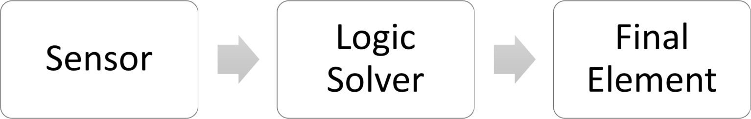
Here is shown an example of how a subsystem can significantly impact the SIL achieved of the safety function.
The function is divided into subsystems, and for each subsystem, the average probability of failure on demand (hp: low demand mode) is calculated, and the architectural constraints (hp. Route 1H) and systematic capacity are included as well.
| Device | PFDavg | SIL Systematic Capability | SIL Architectural Constraints |
|---|---|---|---|
| Sensors | 8,39E-06 | 3 | 2 |
| Logic Solver | 5,09E-07 | 3 | 3 |
| Solenoid | 1,74E-05 | 3 | 3 |
| Actuator | 9,76E-07 | 3 | 2 |
| SIL | PFDavg | SIL PFDavg | SIL Systematic Capability | SIL Architectural Constraints |
|---|---|---|---|---|
| Total | 2,00E-04 | 3 | 3 | 2 |
The SIL obtained is the lowest of the SIL achieved for PFDavg, its systematic capability, and architectural constraints. This is a SIL 2.
The PFDavg and architectural constraints, having fixed the components, can be improved by changing the architecture. Systematic capability is a characteristic parameter of the component that does not vary with the architecture.
Systematic capability, therefore, defines the maximum SIL the component can achieve.
Note: In common language, when a component is defined SIL n capable, this means that it can be used in “up to n” application and not that it can be used as a stand-alone device in SIL n applications.
Logic Solver overview
A logic solver makes decisions about what to do, based on sensor input. Decision rules are often implemented by software or digital/electronic components.
A logic solver can manage both safety and non-safety functions: it is clear that the two parts must be segregated, and the non-safety function must not interfere with the safety function.
A logic solve can be:
- Hardwired, control and decision-making are carried out using relays and contactors
- Solid state, control and decision-making are carried out by a fixed set of arranged and programmed electronic components (no mechanical components)
- Programmable, control and decision-making are carried out by software
Recommended in-depth study
Software Safety ManagementFinal element overview
A final element is a device that receives the command from the logic solver and converts it into a physical movement. The final element interacts with the protected system.
Some examples of final elements:
- Block valves
- Automatic switch
- Break
- Fire fighting protection
The standard suggests using a safety philosophy for the drive of the final element.
Fail-safe causes a machine to return to a safe condition in the event of failure or malfunction.
Fail-safe is not always applicable. In the case of a fire-fighting system, the extinguishing system must be activated by means of the “energized to trip” control, in order to avoid possible safety consequences for spurious trips.
Recommended in-depth study
Types of failure and Architecture examplesSIS validation overview
SIS (Safety Instrumented System) safety validation consists of validating, thorough inspection and testing, that the installed and commissioned SIS and associated SIFs meet the requirements, as set out in the safety requirements specification.
The procedures and techniques used for validation should be calibration procedures, hardware testing, software testing, etc.
All individuals involved in the validation procedures must be defined, including their level of independence.
Some of the validation activities are:
- Verifying the SIS under specific conditions, such as normal operation, emergency, start-up, shutdown, diagnostic function, etc.
- Verifying the SIS interface and the absence of BPCS interference in terms of safety
- Verifying communication between the SIS and the other system
- Checking the device involved in the safety function
- Verifying the system with the relevant documentation
- Software validation
- Validating different types of operating modes
- Verifying test frequencies
Validation activities are repeated after each (interfering!) change to the SIS.
Recommended in-depth study
Functional Safety Management System